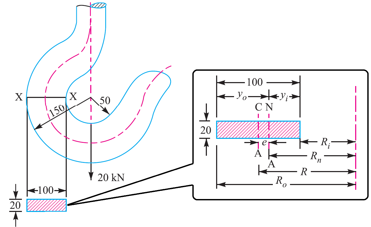
Along with stress buckling is also a critical factor in lifting beams that must be addressed in. The crane hook carries a load of 20 kN as shown in given below Fig.
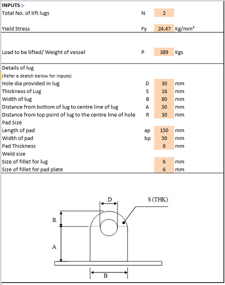
Lifting Lug Design Spreadsheet Calculator
By varying the lengths of chokers a fixed-tilt lifting beam can be made as depicted in Fig.

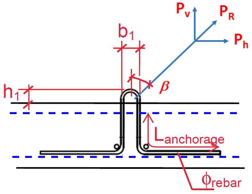
. Dynamic Impact factor Fh fSQRTfxfx2fyfy2fx2 Iy2db223b312. For example if the material weighs 100 lbs. First lifting hook minimum effort.
The full length support feature of this C-hook increases the amount of surface area in contact with the coil minimizing the potential for damage to. Dynamic Amplification Factors Fh for LIGHT Packages. Check Bending and tension stress.
A lifting hook is usually equipped with a safety latch to prevent the disengagement of the. Min 1 ξ. 115 min1ξmax1ξV L.
Al 2009 this paper presents the different methods of stress calculation for lifting hooks based on different assumptions. Tension on Sling T 1 2 V1 2 H1 2 12 Tension on Sling T 1 2 W legs sin a 1 2. Then analyzed the axial load of 2 tons by the.
Other than for slings it appears that there are no inspection criteria for below-the-hook lifting devices in the OSHA. To do so determine the volume of the load and material its composed of with the following formula. Check lug shear stress.
2013 standard Forged Steel Lifting Hooks with Latch Grade 8 to be an initial lifting hook. I did not find the David T. 115 with ξ 03 for fixed crane or on rails and ξ 06 for crane bridge.
Q 1 kNm² for oiled steel mould. B3020 and BTH-1 Design of Below-the-Hook Lifting Devices. Q 3 kNm² for rough timber mould.
First separate the object into rectangles and then calculate the weight of each section individually and then combine them as shown below. Lifting hook design calculation Written By alfonzostraney88785 Saturday March 26 2022 Add Comment Edit. Load weight weight per volume total volume.
1 a H Ha. To attach the load locate the center of gravity position the crane hook directly above the center of gravity and then rig the load so that it will lift level and true. The quantity of effective lifting points may be less than the quantity of real lifting points if the system is not balanced.
They applied curved beam theory Finite Element Method and photo elasticity experiments to obtain the stress field on the hook. Examples of detachable lifting equipment are shown in annex A. An Overview of ASME BTH-1 spreader bars and lifting beams When planning to design lifting beams or any other below-the-hook lifting devices there are many aspects that must be considered beyond finding materials that meets a few basic engineering calculations.
Calculations to be made will include the capacity both of the overall beam and of the loading of the individual lifting points. Another important consideration is the centre of gravity of the load to be lifted together with any accessories and or attachments used - slings grabs shackles hooks magnets vacuum pads etc. Formwork adhesion Ha is calculated through the following equation.
Ha q x A kN A. Expressed in terms of variables noted in Fig. Volume 1 24 cubic feet.
The section at X-X is rectangular whose horizontal side is 100 mm. Click here to Download this Software -httpsbitly2CBd7UcWelcome. Lifting Hook Design JWN3C30A - Free download as Excel Spreadsheet xls PDF File pdf Text File txt or read online for free.
Calculation Reference Machine Design Strength of Welds Design of Lifting Equipment Calculation Preview. 1 5 min 1 xi. Heres how you would calculate the load weight of an irregular shaped object made out of concrete.
Lifting Hook Design JWN3C30A. The design of below-the-hook lifting devices are standardized in the United States by ASME B3020 and further detailed in Below-the-Hook Lifting BTH-1-2008 Design of Below-the-Hook Lifting Devices. Area of contact between the mould and the concrete unit when starting to lift.
The first step is to create a lifting hook by ISO 7597. Max 1 ξ V L. Max 1 xi cdot V_ L.
Design calculations for lifting lug welded onto equipment like pressure vessels etc. Q 2 kNm² for varnished timber mould. For producing a safe reliable design This is the most widely used lifting lug design standard.
Steve Haberli shaberli Submitted On. Lifting Lug Design Spreadsheet Calculator. Lifting lug calcsxls Lifting lug calcsxls.
Find the stresses in the inner and outer fibres the given section. F1min Gconc 2 Gsteel a1 b 1 p F1min 1101 2 033 183 366 1 20 F1min 454kN Second lifting hook maximum effort. ASME BTH-1 Design of Below-The-Hook Lifting Devices governs the design of lifting lugs for industries.
This excel app can be used to calculate the lift factors and lifting point loads for a s. 2 2 2 sinq long sling length. Engineering Excel Spreadsheet Downloads Welding Design and Engineering Pressure Vessel Design and Engineering.
Volume 1 Top 4 feet x 2 feet x 3 feet. 3C the sling lengths can be calculated using the following formulae. 2 a H Ha.
A lifting hook is a device for grabbing and lifting loads by means of a device such as a hoist or crane. I found the BTH-1-2008 publication commentary sections very usefull. However As such standards do not clearly address the local stress calculation steps Finite Element Analysis is performed using various.
Lifting Lug Design Spreadsheet Calculator. Crane Hook Design Problem. F2max Gconc 2 Gsteel a2 b γdyn γα 1 p F2max 1101 2 033 183 366 16 10086 1 20 F2max 1099kN.
COUNTER BALANCED C-HOOKS This Model 624 C-hook has a lower member length that equals the maximum coil width. Dynamic factor. As a result different methods used to obtain the stress field on.
2
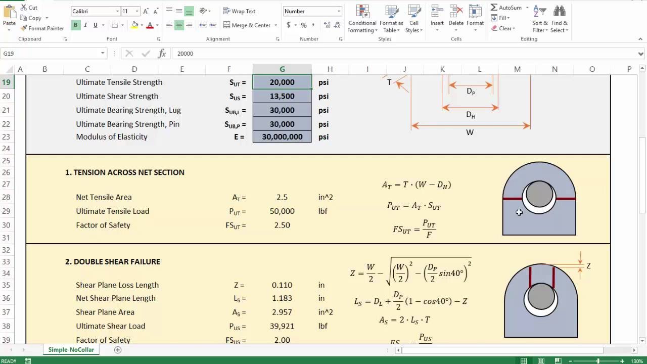
4 Lifting Lug Analysis Simplified Youtube

Lifting Lug Design With Example What Is Piping

Technical Drawing Of Hook Number 12 Download Scientific Diagram
2
Crane Hook Design Problem Sample Extrudesign
Rys Precast Lifting Design
Design Analysis And Weight Optimization Of Crane Hook A Review Semantic Scholar
0 comments
Post a Comment